Summary
The Back-Projection (BP) product shows the beamformed time history and location of coherent short period P-wave energy generated by large earthquakes observed at three regional arrays and across the Global Seismic Network. These are generated following all global M6.5+ earthquakes. The back-projections typically take less than 10 minutes to compute, however arrival of event triggers, travel time of P-waves, downloading of data and shared DMC computing resources delays publication of results in SPUD to about an hour after origin time. These are fully automated and not reviewed by a human.
Quicklinks
- Go to back-projections
- BackProjection Python 3 code (GitHub)
- Citations
Description
These back-projections are good for:
These are meant to be a standardized blunt tool to image the time and space history of high frequency P-waves from large earthquakes. Sometimes, overall rupture features (duration, directivity, length) can be inferred for larger, M > ~7.5, events when two or more arrays are in general agreement with respect to the time and location of bursts of energy. For smaller events, M < ~7.0, rupture characteristics are seldom reliable due to short rupture lengths, however distinguishing between a simple rupture and an earthquake doublet is sometimes noticeable. These can also show the absolute location of smaller, more point-source like, earthquakes as imaged by the particular receiving array within the 1D reference model.
These back-projections are not good for:
Artifacts abound and a growing number of fancier approaches and higher resolution results using careful manual processing are appearing in the literature. Caution should be taken to not over-interpret secondary features or a single array’s results for a given earthquake. Forward modeling with synthetic seismograms computed from finite-fault models shows that for some source-receiver array geometries strong artifacts suggesting rupture complexity can sometimes be reproduced from relatively simple models. Finally, these results are fully automated and similar approaches in the research literature will often contain 'better' results due to more advanced methods and manual attention to data quality and processing results. Bad back-projections are often the result of bad data selection. Caveat emptor.
Data selection
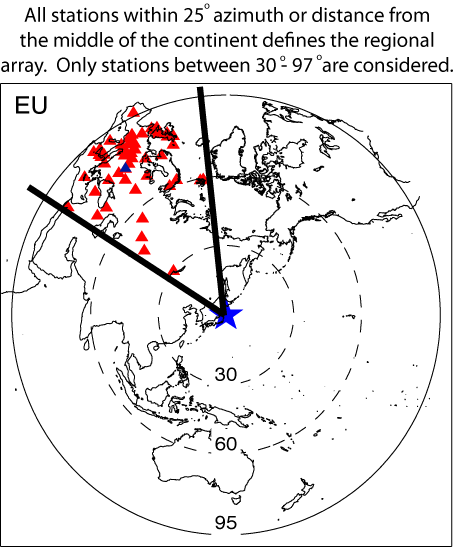
Right: Virtual networks are formed by choosing stations within 25 degrees distance or azimuth to the center of three continents (NAmerica, EUrope, AUstralia). The Global Seismic Network is also used, but requires data to be filtered at lower frequencies.
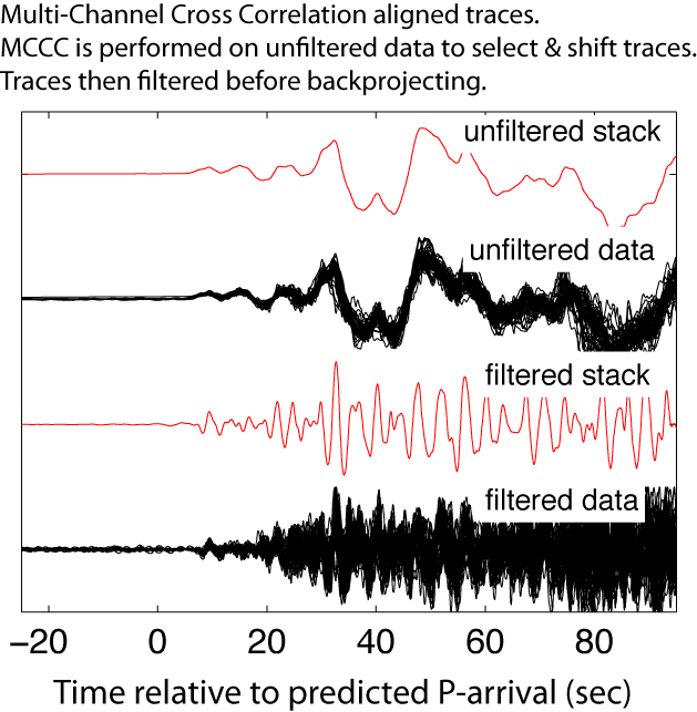
Below: All available BHZ data are then aligned using a Multi-Channel Cross Correlation scheme. The length of the cross-correlation window is based on a short-term average/long-term average sliding window and will be short for impulsive events and long for emergent events. Finally, the algorithm resamples the network to only choose the stations with the highest average cross-correlation coefficient and at least one degree distance to it’s nearest neighboring stations. The algorithm used works well for most earthquakes, but sometimes the alignments are clearly bad. In these rare instances, back-projection results will clearly suffer.
Back-projection processing
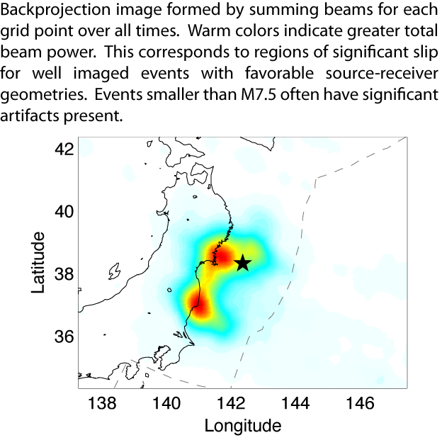
Back-projections are performed by beam forming (stacking) energy to a flat grid around the source region with variable spatial resolution scaled by the magnitude of the earthquake. A sliding 5 sec wide cosine tapered window is used to average the beams to form back-projection images in increments of 1 sec. Before generating the back-projection animations, the images are then averaged over a 10-30 sec tapered window, depending on the magnitude, in order to stabilize the results and reduce artifacts. Static images of the cumulative back-projection stack are given which are formed by summing the images over all times for which back-projections are calculated. Warmer colors indicate greater beam power. In the movies, a red circle shows the location of the peak beam power when absolute beam powers are low.
Stacking
When beam forming, many stacking approaches can be used. Linear stacking tends to be more ‘true’ to amplitudes, though for many events, results can be very noisy. N-th root stacking offers greater enhancement of signal to noise ratio and highlights coherent bursts of high frequency energy. Square-root stacking is chosen for this product. Higher-root stacking also works well, though secondary features can become muted.
Peak Ampliutde vs Time
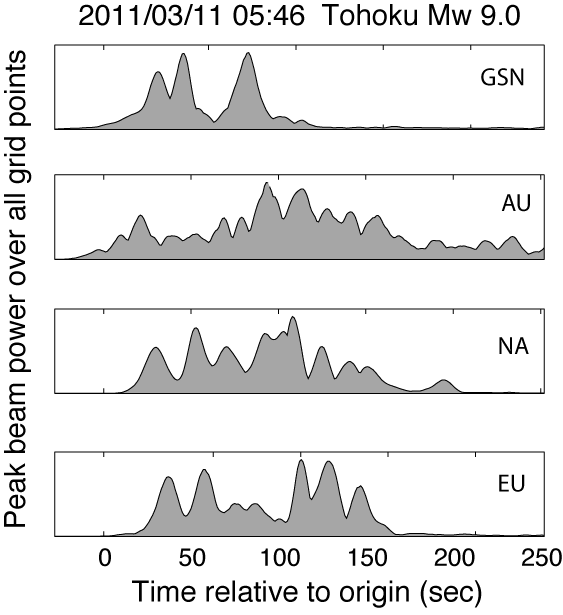
Each back-projection movie also contains a plot of the peak beam power over all grid points as a function of time. Since this is using Nth-root stacking, this does not necessarily correspond to the amount of slip or the moment rate function, although often times, results are consistent with those. In the example here for the four arrays imaging the Tohoku rupture, all suggest a duration of about 150 seconds. The AU results are quite noisy since they only used data from 4 stations. For well imaged events, peaks of sub-events tend to align, though not always, e.g. features at ~130 and ~150 sec for the GSN array. Many factors influence these, including processing parameters such as the window length used to average results. At the bottom of the back-projection page in SPUD, text files with peak beam power (and their Lat/Lon location) as a function of time relative to origin are given for both the data and the synthetic ARF.
Artifacts (technical)
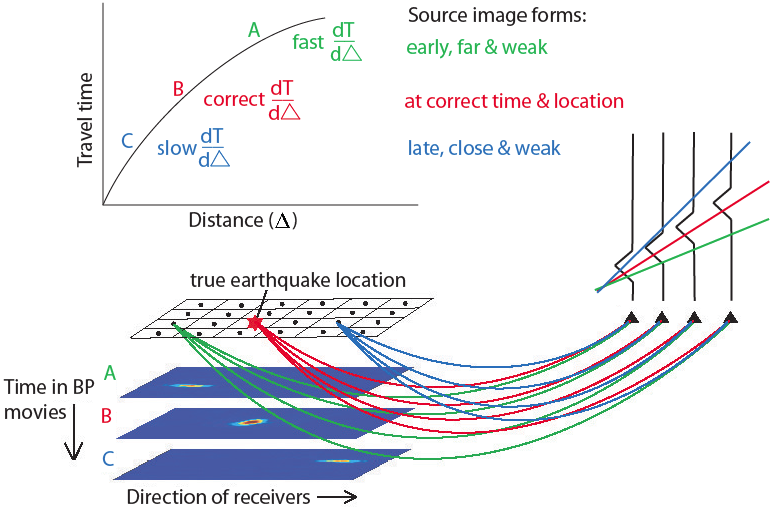
In the back-projection movies, energy seems to smear or ‘swim’ in the direction of the array as time marches forward. This happens because there is a tradeoff between origin time and distance from the receiving array for stacked energy. Ideally the true absolute location of bursts of energy will always be revealed by the back-projections, however the results are influenced by many factors including filtering & smoothing in processing, complicated Green’s function (dipping slab, depth phases), radiation pattern effects and variable slip dip/rake/direction as the rupture propagates. Limited source-receiver geometry can also produce unintuitive constructive & destructive interference and is often the greatest source of noise. Koper et al., 2011 contains further technical details on back-projection images and artifacts.
Array Response Function
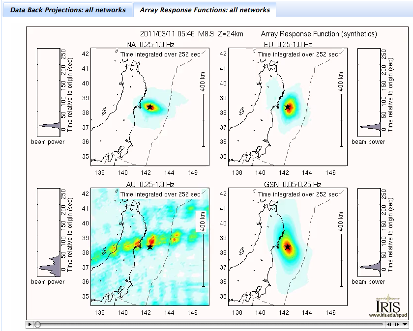
In order to estimate the effect of limited source-receiver geometry for a given array configuration, an Array Response Function (ARF) is generated alongside the data. To estimate this, the exact same stations and processing are used, except rather than using data seismograms, the traces are replaced with point-source triangle function synthetics. That is, traces whose amplitudes are zero everywhere, except at the predicted arrival time of the P-wave, which has a 3 sec wide triangle function. Back-projection results with complicated ARF should be viewed judiciously. ARFs are often asymmetric in space and in time due to constructive interference and time averaging artifacts. Note: As of June 2012, an additional layer of QCing was added to all back-projections which effecively culls those which have ARFs that are too wide or distorted such as those from the AU virtual array in the figure.
Local Maxima
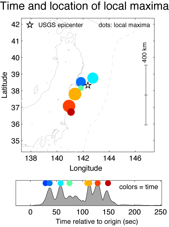
Included in the summary figures are the time and location of local maxima. The colors correspond to relative time and the diameter to relative beam power. For well-imaged events, the dots will outline the major sub-events. An image with dots scattered all over usually indicates a poorly imaged rupture. These images offer only a quick and dirty static look at the rupture by the imaging array.
Citations and DOIs
To cite the IRIS DMC Data Products effort
- Trabant, C., A. R. Hutko, M. Bahavar, R. Karstens, T. Ahern, and R. Aster (2012), Data Products at the IRIS DMC: Stepping Stones for Research and Other Applications, Seismological Research Letters, 83(5), 846–854, https://doi.org/10.1785/0220120032.
To cite the IRIS DMC Back-Projection data product or reference use of its repository:
- IRIS DMC (2011), Data Services Products: BackProjection P-wave back-projection rupture imaging, https://doi.org/10.17611/DP/BP.1.
To cite a particular Back-Projection:
– select the Back-Projection of interest
– click on Citations to obtain its DOI
– insert the DOI in below reference:
- IRIS DMC (2011), Data Services Products: BackProjection P-wave back-projection rupture imaging, doi:INSERT DOI HERE.
References:
Ishii, M., Shearer, P.M., Houston, H., & Vidale, J.E., 2005, Extent, duration and speed of the 2004 Sumatra-Andaman earthquake imaged by the Hi-Net array. Nature 435(7044), 933-936, https://doi.org/10.1038/nature03675.
Xu Y., K.D. Koper, O. Sufri, L. Zhu, and A. Hutko, Rupture imaging of the Mw 7.9 12 May 2008 Wenchuan earthquake from back projection of teleseismic P waves, Geochem. Geophys. Geosyst., 10, Q04006, https://doi.org/10.1029/2008GC002335, 2009.
Keith D. Koper, Hutko, A.R., Lay, T., and Sufri, O., maging short-period seismic radiation from the 27 February 2010 Chile ( 8.8) earthquake by back-projection of P, PP, and PKIKP waves, J. Geophys. Res., 117, B2, https://doi.org/10.1029/2011JB008576, 2012.
Credits
- Alexander Hutko
Timeline
- 2011-10-01
- BackProjection R1 (Fortran) online
- 2021-11-01
- BackProjection R2 (Python 3) online


